Wake-on-GPIO
Alternative title: How to spend an afternoon at Bastli.
Wake-on-LAN has a few issues that I personally don’t like. The primary thing that I don’t like is that it relies on the mainboard and network interface to be not-quite-shutdown. This leads to some unnecessary power draw while the PC/server is supposed to be shut down.
In addition to that, the way WOL works bothers me. Basically, the OS needs to shut down in a very specific way and instruct the NIC to wait for WOL-packets. Every single time. It is not a one-off configuration option that is stored on a NIC (at least not on my hardware). This leads to WOL not working when a PC didn’t experience a clean shutdown. This happened to me multiple times, sometimes because power went out for a bit, other times simply because the PC crashed.
These issues can sometimes be remedied in various ways (tuning BIOS settings, etc) but I believe there is be a better way that does not require tuning various settings to get to a baseline of reliability and power efficiency.
The solution is obviously to hijack the power button pins on the motherboard using the raspberry pi GPIO.
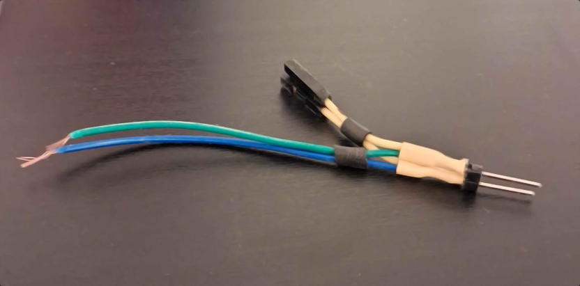
The first thing I did was create a fork for the pins inside the PC – I don’t want to modify the motherboard or the cable of the existing power button:
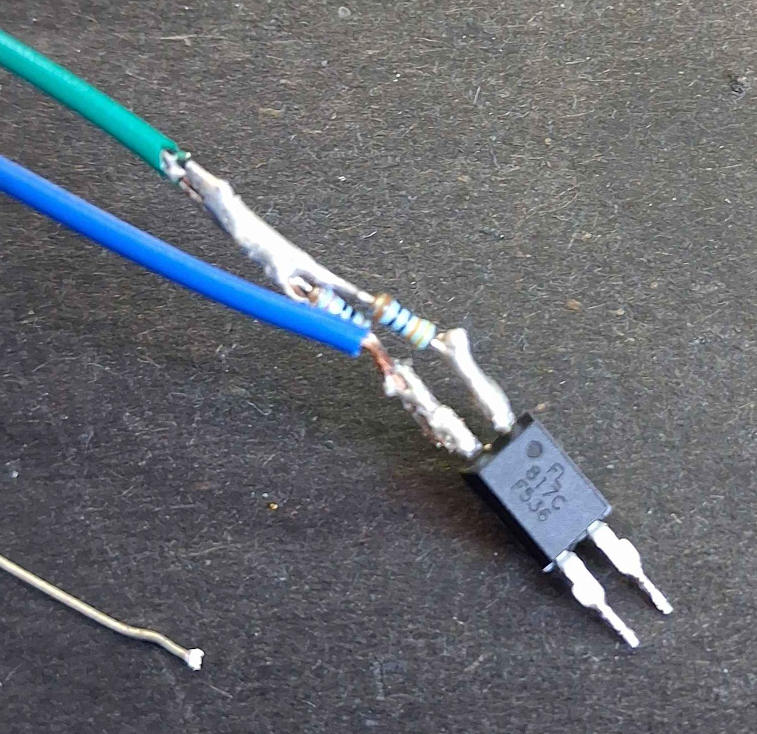
Next I needed to find out how to wire this to the raspberry pi. I cannot simply connect these cables to raspberry pi pins, as the PC cables are a completely different circuit to the pi. Additionally, I don’t need to pull either of these wires “high” or “low”, I need to connect the two wires for a short time for the mainboard to detect that as a button press. A component I found that works for this job is the PC817C octocoupler – given a voltage applied on the input side of the component, it allows current to flow on the output side of the component, while both sides are electrically isolated from each other. It essentially acts as a solid state relay for my purposes.
The way this works is that on the input side it is wired to a small light emitting diode, and on the output side there is a phototransistor that allows current to flow when being illuminated. Diagrammatically the setup then looks as follows:

Not mentioned so far are the two resistors on the input side. I used a 330Ω resistor to limit the current going through the octocoupler, and a 10kΩ resistor to pull the pin down in case the GPIO signal might be floating during boot of the pi. This setup should lead to a current of 10mA (given the pi’s 3.3V GPIO voltage) when enabled, which is within the limits of both the raspberry pi and this specific octocoupler.
In practice this turned out uglier than expected, attributable to me not having soldered a thing in ages.
Not to fear though, a bit of shrink tube can conceal the solder-job, while a tape-based cable connection can distract from it altogether:
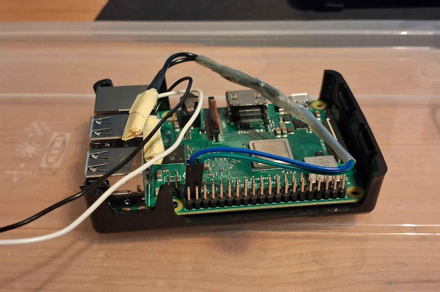
Everything assembled, it is time for some software.
This turned out quite easy on my raspberry pi, as FreeBSD comes with the gpioctl utility.
All that is needed is this short sequence of shell commands:
GPIODEV=/dev/gpioc0
PIN=26

gpioctl -f $GPIODEV -c $PIN OUT
gpioctl -f $GPIODEV $PIN 1
sleep 0.2
gpioctl -f $GPIODEV $PIN 0
Somewhere at this point I realized that I can also use this to turn off my PC – if I press the power button for a few seconds it should shut down in pretty much all circumstances.
Closing words
Is it completely stupid? yes
Is the build quality of this entire thing problematic? maybe, but I believe the voltages involved are small enough to not worry about this.
Do I think it’s superior to Wake-on-LAN? also yes
Before I stop writing it might be worth mentioning that the PiKVM also supports power management via the power button pins, while being much higher quality – I found this out after wondering if someone else made something similar before (obviously someone did).